모든 글
약 38분 분량 학습 프로젝트/토이 커널

네트워킹: virtio-net과 미니 TCP/IP 스택
목차

0. 들어가며

지금까지 커널은 부팅, 페이징, 프로세스, 파일시스템, 그리고 6편의 멀티코어까지 디스크 영역을 다뤘습니다.
이번엔 마지막 조각, 네트워크입니다.

네트워킹은 xv6 랩 중에서도 코드 표면이 가장 넓습니다.
하드웨어(NIC, Network Interface Card, 네트워크 카드)부터 이더넷·ARP·IP·UDP까지, 계층을 손으로 직접 쌓아야 비로소 패킷 하나가 나갔다 들어옵니다.
이 글의 목표는 한 줄로 요약됩니다. “패킷이 바이트 배열에서 어떻게 조립되고, NIC를 거쳐 나갔다 돌아오는가”를 끝까지 손으로 만져본다.

그래서 이 글은 네트워크 스택을 계층 순서대로 쌓아 올립니다.
NIC 드라이버(virtio-net)로 프레임을 주고받는 토대를 깔고 → 이더넷/ARP로 게이트웨이 MAC을 알아내고 → 그 위에 IP를 얹고 → ICMP로 IP 계층을 검증하고 → UDP로 포트 다중화를 더하고 → 마지막에 DNS로 도메인을 해석합니다.
쌓는 순서는 아래 계층부터 위로입니다. 아래 계층이 동작해야 위 계층을 검증할 수 있기 때문입니다. 프레임을 못 보내면 ARP를 못 하고, MAC을 모르면 IP를 못 얹고, IP가 안 되면 UDP도 의미가 없습니다.

검증 환경은 QEMU의 user 네트워킹(SLIRP) 입니다.
SLIRP는 게이트웨이(10.0.2.2)·DNS(10.0.2.3)·DHCP를 흉내내는 가상 네트워크라, 호스트 설정 없이도 ARP·ICMP·DNS에 응답해줍니다.
우리 게스트는 SLIRP가 기본으로 나눠주는 주소 10.0.2.15를 씁니다.

이 글의 스택은 UDP까지입니다. TCP는 일부러 10편으로 미뤘습니다. 연결 상태머신·재전송·혼잡 제어를 제대로 하려면 그 자체로 한 편이 필요합니다. 왜 여기서 끊는 게 합리적인지는 6절에서 따로 설명합니다.

1. virtio-net 드라이버가 풀어야 하는 진짜 문제

CPU와 메모리는 디지털 신호만 다룹니다. 그런데 “이 바이트 묶음을 선 너머로 보내라”, “방금 선에서 도착한 바이트를 받아라” 같은 물리적인 일은, 코드가 어떻게 NIC에게 시킬까요?

NIC(Network Interface Card)는 외부 장치입니다.
우리 커널이 직접 전선을 흔들 수는 없으니, NIC에게 일을 시키는 약속된 방법이 필요합니다.
QEMU virt에서 그 약속이 바로 virtio, 게스트와 가상 장치가 공유 메모리의 링(ring) 자료구조로 작업을 주고받는 표준입니다.

좋은 소식이 하나 있습니다. 저는 이미 3편에서 virtio-blk 디스크 드라이버를 만들었습니다.
그때 만든 전송 계층(virtio-mmio: 디스크립터 체인 + available/used 링 + 기능 협상)이 virtio-net에도 거의 그대로 재사용됩니다.
디스크든 네트워크든, 게스트가 메모리에 버퍼를 만들어 available 링에 넣고 QUEUE_NOTIFY로 알린 뒤 used 링이 갱신될 때까지 폴링하는 흐름은 동일합니다.

virtio-blk vs virtio-net: 무엇이 다른가

같은 전송 계층 위에 있지만, 디스크와 네트워크는 몇 군데서 갈립니다.

구분virtio-blk (디스크, 3편)virtio-net (네트워크, 이 글)
device-id21
큐 개수1개2개: 큐0=수신(RX), 큐1=송신(TX)
버퍼 앞 헤더virtio_blk_req(요청 헤더)12B virtio_net_hdr(체크섬 오프로드·GSO 정보)
데이터 방향요청마다 read 또는 writeRX는 device→게스트, TX는 게스트→device로 고정
흐름요청 한 건 → 응답 한 건RX는 버퍼 미리 깔고 폴링, TX는 보낼 때마다

net_init은 먼저 QEMU virt의 8개 virtio-mmio 슬롯(0x10001000부터 0x1000씩)을 훑어 device-id가 1인 슬롯을 찾습니다.
그다음 status 비트를 단계적으로 올리며(ACKNOWLEDGEDRIVERFEATURES_OKDRIVER_OK) 장치를 깨우는데, 이 핸드셰이크 자체는 디스크 때와 똑같습니다.

기능 협상: 일부러 거의 다 끈다

디바이스는 체크섬 오프로드, GSO, 머지 버퍼, 제어 큐 같은 화려한 기능을 잔뜩 제공하겠다고 합니다. 우리는 무엇을 받아야 할까요?

학습용 스택의 정답은 “최대한 끈다” 입니다.
수락한 기능은 장치와 우리가 모두 쓰기로 약속한 기능이라, 켤수록 드라이버가 지원해야 할 코드가 늘고 버그도 늡니다.
그래서 net_init은 하위 32비트에서 VIRTIO_NET_F_MAC(MAC을 config에서 읽는 기능) 하나만 남기고, 상위 32비트에선 VERSION_1만 수락합니다.

// 하위 32비트: MAC만 받고 체크섬/머지버퍼/제어큐는 끈다
NR32(MMIO_DEVICE_FEAT_SEL) = 0;
uint32 lo = NR32(MMIO_DEVICE_FEAT);
lo &= (1u << VIRTIO_NET_F_MAC); // MAC만 유지
NR32(MMIO_DRIVER_FEAT_SEL) = 0;
NR32(MMIO_DRIVER_FEAT) = lo;
// 상위 32비트: VERSION_1만 수락(헤더 12바이트 고정)
NR32(MMIO_DEVICE_FEAT_SEL) = 1;
uint32 hi = NR32(MMIO_DEVICE_FEAT) & 0x1; // 비트0 = VERSION_1
NR32(MMIO_DRIVER_FEAT_SEL) = 1;
NR32(MMIO_DRIVER_FEAT) = hi;

체크섬 오프로드를 끈다는 건 체크섬을 우리가 직접 계산한다는 뜻입니다(3절에서 다룹니다).
머지 버퍼를 끄면 한 프레임이 항상 버퍼 하나에 들어와서 RX 처리가 단순해지고, VERSION_1만 받으면 virtio_net_hdr항상 12바이트 고정이라 파싱이 깔끔해집니다.
화려함을 포기하는 대신 코드가 단순해지는 전형적인 학습용 트레이드오프입니다.

RX: 버퍼를 미리 디바이스에 쥐여준다

수신에는 한 가지 비대칭이 있습니다.
송신은 우리가 보낼 때 버퍼를 만들면 되지만, 수신은 패킷이 “언제 올지” 모릅니다.
그래서 RX는 빈 버퍼를 미리 디바이스에 등록해두는 방식을 씁니다. 즉 수신 큐는 디바이스가 언제 프레임을 넣어도 되도록 항상 “사용 가능한 빈 버퍼”를 유지해야 합니다(그래서 처리한 버퍼를 곧바로 다시 채워 넣습니다).
RX 큐에 빈 버퍼 8개를 깔아두면, 패킷이 도착할 때 디바이스가 그중 하나에 써넣고 used 링을 갱신합니다.

// RX 버퍼 8개를 device-writable로 등록
for (int i = 0; i < NUM; i++) {
rxbuf[i] = (uint8 *)kalloc();
rxq.desc[i].addr = (uint64)rxbuf[i];
rxq.desc[i].len = BUFSZ;
rxq.desc[i].flags = VRING_DESC_F_WRITE; // 디바이스가 여기에 쓴다
rxq.avail->ring[i] = i;
}
rxq.avail->idx = NUM;

여기서 VRING_DESC_F_WRITE 플래그가 핵심입니다. “이 버퍼는 디바이스가 쓰는 쪽”이라는 표시죠(TX 버퍼엔 이 플래그가 없고, 디바이스가 읽는 쪽입니다).
이후 eth_rx는 used 링을 폴링하다가 used->idx가 갱신되면 버퍼에서 프레임을 꺼내고, 앞 12바이트(virtio_net_hdr)를 건너뛴 뒤 다시 그 버퍼를 큐에 돌려줍니다(반납해야 다음 패킷을 받을 수 있습니다).

// eth_rx — 도착한 프레임에서 12바이트 헤더를 건너뛰고 복사, 버퍼는 큐에 반납
uint32 len = e->len; // hdr + 프레임 바이트 수
if (len > NETHDR) { // NETHDR = 12
flen = len - NETHDR;
copy(out, rxbuf[id] + NETHDR, flen); // virtio_net_hdr 건너뛰고 복사
}
rxq.avail->ring[rxq.avail->idx % NUM] = id; // 버퍼를 디바이스에 다시 제공

MAC 주소는 디바이스 설정공간(MMIO 오프셋 0x100)에서 6바이트 읽어옵니다.
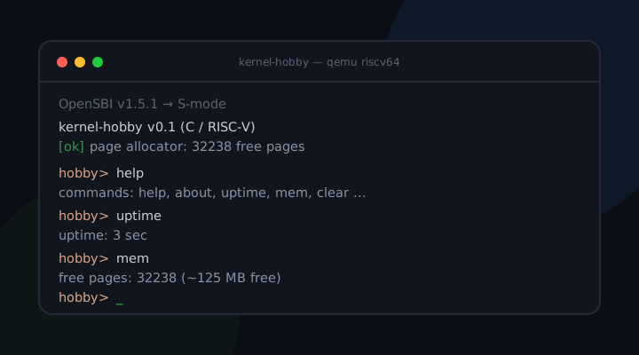
초기화가 끝나면 이 줄이 뜹니다.

[ok] virtio-net ready, mac 52:54:00:12:34:56

핵심 질문에 대한 답: 코드가 NIC에게 일을 시키는 방법은 “공유 메모리 링에 버퍼를 올리고 QUEUE_NOTIFY로 종을 친 뒤 used 링을 폴링”하는 것이고, 이건 디스크 때와 똑같습니다. 네트워크에서 새로 생기는 건 큐가 둘(RX/TX) 이라는 점과 모든 프레임 앞 12바이트 헤더, 이 둘뿐입니다.

2. 이더넷과 ARP: 첫 대화 상대 찾기

이제 프레임을 주고받을 수 있으니, 실제로 누군가와 대화할 차례입니다.
첫 상대는 게이트웨이(10.0.2.2)입니다.

ARP가 풀어야 하는 진짜 문제

우리는 게이트웨이의 IP(10.0.2.2)는 압니다. 그런데 이더넷 프레임의 수신자 칸엔 IP가 아니라 MAC 주소를 적어야 합니다. IP만 알고 MAC을 모르는 상대에게, 어떻게 첫 프레임을 보낼까요?

여기에 계층의 본질이 있습니다.
이더넷은 MAC 주소로, IP는 IP 주소로 길을 찾습니다.
이 둘은 다른 주소 체계라서, “IP X를 가진 장치의 MAC은 무엇인가”를 알아내는 번역 과정이 반드시 필요합니다.
그 번역기가 ARP(Address Resolution Protocol)입니다.

그런데 닭과 달걀 문제가 있습니다. MAC을 모르는데 어떻게 물어보지? (ARP의 핵심은 상대 하나에게 콕 집어 묻지 않고 LAN 전체에게 브로드캐스트로 묻는 데 있습니다.)
ARP의 해법은 브로드캐스트입니다.
“이 LAN에 10.0.2.2 가진 사람? MAC 좀 알려줘”를 모두에게(ff:ff:ff:ff:ff:ff) 외치고, 해당 IP 주인만 유니캐스트로 답합니다.

// "who-has 10.0.2.2" 브로드캐스트 (28바이트 ARP 패킷)
put16(a + 0, 1); // htype = Ethernet
put16(a + 2, 0x0800); // ptype = IPv4
a[4] = 6; a[5] = 4; // hlen=6(MAC), plen=4(IPv4)
put16(a + 6, 1); // oper = request
copy(a + 8, my_mac, 6); copy(a + 14, MY_IP, 4); // 보내는 나
zero(a + 18, 6); copy(a + 24, target_ip, 4); // 찾는 대상(MAC은 비움)

arp_resolve는 이 요청을 보낸 뒤 used 링을 폴링하며 oper=2(reply)이고 sender IP가 우리가 찾던 IP인 프레임을 기다립니다.
도착하면 그 안의 sender MAC(a + 8)을 꺼내 저장합니다.

반대 방향도 있어야 합니다.
누가 우리 IP(10.0.2.15)를 물으면 우리도 응답해야 합니다(arp_maybe_reply).
이게 없으면 상대가 우리에게 패킷을 보내고 싶어도 우리 MAC을 몰라 못 보냅니다.
그래서 ARP를 기다리는 모든 수신 루프는, 그 사이 들어온 ARP 요청도 같이 처리합니다.

// 들어온 프레임이 "우리 IP"를 묻는 ARP 요청이면 reply를 돌려준다
if (get16(a + 6) != 1) return; // request만
if (!eq4(a + 24, MY_IP)) return; // 우리 IP를 묻는 게 아님
put16(r + 6, 2); // oper = reply
copy(r + 8, my_mac, 6); copy(r + 14, MY_IP, 4); // "내 MAC은 이거야"
copy(r + 18, a + 8, 6); copy(r + 24, a + 14, 4); // 요청자에게 돌려보냄

부팅 로그에서 이 대화가 그대로 보입니다.

[net] ARP who-has 10.0.2.2 (gateway) ... is-at 52:55:0a:00:02:02

이 한 줄이 뜬다는 건 의외로 큰 사건입니다.
프레임을 보냈고(드라이버 TX + 이더넷 인코딩), 응답이 돌아왔고(드라이버 RX + 폴링), ARP 요청/응답 형식이 맞았다는 걸 한 번에 증명합니다. 다시 말해 브로드캐스트 요청과 유니캐스트 응답이 둘 다 성공했다는 뜻입니다.
1절의 드라이버와 2절의 이더넷/ARP가 한 줄로 맞물리는 순간입니다.

흔한 오해 정정: “ARP는 라우터를 거쳐 멀리 있는 IP의 MAC도 알아낸다”고 오해하기 쉬운데, 그렇지 않습니다. ARP는 같은 LAN(브로드캐스트가 닿는 범위) 안에서만 동작합니다. 인터넷 저편의 서버로 보낼 때도 우리가 ARP로 알아내는 건 그 서버의 MAC이 아니라 게이트웨이의 MAC입니다. 일단 게이트웨이에게 넘기면 그다음은 게이트웨이가 라우팅합니다. 그래서 우리 스택이 게이트웨이 MAC 하나만 알면 바깥으로 나가는 모든 패킷을 보낼 수 있습니다.

3. IP·ICMP·UDP: 계층을 포개기

게이트웨이 MAC을 알았으니, 이제 이더넷 프레임 위에 차곡차곡 계층을 얹습니다.

IP가 풀어야 하는 진짜 문제

이더넷은 같은 LAN 안에서 MAC끼리만 전달합니다. 그런데 LAN을 넘어 전 세계 어디든 닿으려면? 그리고 도착한 바이트 묶음이 손상되지 않았다는 걸 어떻게 알까요?

IP는 “전 세계 통용 주소”(IP 주소)를 정의해 LAN을 넘는 라우팅을 가능하게 합니다.
우리가 만드는 IP 헤더는 20바이트입니다. 버전/헤더길이(0x45), 전체 길이, TTL(64), 상위 프로토콜 번호(ICMP=1, UDP=17, TCP=6), 출발/도착 IP, 그리고 헤더 체크섬.

공용 체크섬: IP·ICMP·UDP가 한 함수를 공유

손상 검출을 담당하는 게 체크섬입니다.
인터넷 프로토콜들은 모두 같은 16비트 1의 보수 체크섬을 쓰기로 약속해서, 함수 하나로 전부 커버합니다.

static uint16 cksum(const uint8 *data, int len) {
uint32 sum = 0;
for (int i = 0; i + 1 < len; i += 2) sum += get16(data + i); // 16비트씩 합산
if (len & 1) sum += (uint16)data[len - 1] << 8; // 홀수 바이트 보정
while (sum >> 16) sum = (sum & 0xffff) + (sum >> 16); // 자리올림 접기
return ~sum & 0xffff; // 1의 보수
}

받는 쪽은 헤더 전체(체크섬 필드 포함)를 같은 방식으로 접습니다. 자리올림까지 접은 합이 0xFFFF(전부 1)면 정상이고, 그 1의 보수가 0입니다. 즉 위 checksum()을 그대로 다시 돌려 0이 나오면 “손상 없음”으로 봅니다.
이 단순한 산수 하나가 IP·ICMP·UDP·TCP 전부의 무결성 검사를 담당합니다.

ICMP ping: IP 계층을 검증하는 가장 깔끔한 방법

IP 헤더를 제대로 만들었는지, 체크섬 계산이 맞는지, 어떻게 한 방에 확인할까요?

ping(ICMP echo)입니다.
게이트웨이로 “echo request”(type=8)를 보내면 “echo reply”(type=0)가 돌아옵니다.

// ICMP echo request — type=8, 32바이트 페이로드, 자체 체크섬
icmp[0] = 8; icmp[1] = 0; // type=echo request, code=0
put16(icmp + 4, 0xabcd); // id
put16(icmp + 6, 1); // seq
for (int i = 0; i < 32; i++) icmp[8 + i] = (uint8)('a' + i % 26);
put16(icmp + 2, cksum(icmp, 8 + 32)); // ICMP 체크섬
// → 20바이트 IP 헤더(proto=1)로 감싸 게이트웨이 MAC으로 eth_tx

여기에 학습 환경의 한 가지 이점이 드러납니다. SLIRP는 게이트웨이 ping을 자기 내부에서 응답합니다.
즉 바깥 인터넷이 한 줄도 안 열려 있어도, ping이 왕복하면 그것만으로 우리 IP 헤더 빌드 + 체크섬 + 드라이버 송수신이 전부 정확하다는 게 증명됩니다.
오프라인에서도 IP 계층을 검증할 수 있는 겁니다. (따라서 실제 인터넷까지 패킷이 나간 건 아니고, SLIRP가 게이트웨이 역할을 대신 응답해 줍니다.)

[net] ping 10.0.2.2 ... reply

UDP와 의사헤더: 같은 호스트 안에서 누구에게?

IP는 “어느 호스트로”까지만 책임집니다. 그런데 한 호스트 안에서도 DNS, 시간 동기화, 게임 등 여러 응용이 동시에 통신합니다. 도착한 패킷을 그 안의 누구에게 줘야 할까요?

그 “누구”를 가리키는 게 포트 번호고, 포트를 더해 응용끼리 구분(다중화)하는 가장 단순한 프로토콜이 UDP입니다.
UDP는 IP 위에 8바이트 헤더(출발 포트, 도착 포트, 길이, 체크섬)만 얹습니다.

UDP 체크섬엔 특이한 점이 하나 있습니다. 의사헤더(pseudo-header) 입니다.
UDP는 자기 헤더+데이터뿐 아니라, 그 앞에 가상의 헤더(출발 IP + 도착 IP + 프로토콜 번호 + UDP 길이)를 상상으로 덧붙여 함께 합산합니다.

// UDP 체크섬: 의사헤더(src IP + dst IP + proto + udplen) + UDP 세그먼트
uint32 sum = 0;
sum += get16(MY_IP) + get16(MY_IP + 2); // 출발 IP
sum += get16(dst_ip) + get16(dst_ip + 2); // 도착 IP
sum += 17 + udplen; // proto=UDP(17) + 길이
for (int i = 0; i + 1 < udplen; i += 2) sum += get16(pkt + 20 + i);

왜 IP 주소까지 섞을까요?
“이 UDP 세그먼트가 정말 이 출발지→도착지 쌍으로 가는 게 맞나”까지 한 번 더 검증하려는 설계입니다.
헤더가 중간에 엉뚱하게 바뀌어 다른 목적지로 잘못 전달되는 경우를 잡아내려는 안전장치입니다.
(참고로 10편의 TCP도 똑같은 의사헤더 방식을 씁니다. 그래서 UDP에서 한 번 익혀두면 TCP 체크섬은 그대로 따라옵니다.)

한 장으로 보는 계층

지금까지 포갠 계층을 정리하면 이렇습니다. 패킷 하나는 이 헤더들이 양파처럼 겹친 결과물입니다.

계층우리 코드주소/식별자검증 수단
이더넷eth_tx/eth_rxMAC(6B) + ethertype
ARParp_resolveIP↔MAC 번역who-has/is-at 로그
IPudp_tx/icmp_ping의 헤더IP(4B) + proto헤더 체크섬
ICMPicmp_pingtype(8/0)echo 왕복(ping)
UDPudp_tx/udp_rx포트(2B)의사헤더 체크섬

핵심 교훈: 위 계층들은 모두 같은 16비트 체크섬 함수 하나에 기댑니다. “공통 메커니즘을 한 번 잘 만들어 여러 계층이 공유한다”는 건 실제 TCP/IP 스택의 설계 철학이기도 합니다. 우리 미니 스택이 작아도 그 구조는 진짜를 닮아 있습니다.

4. DNS: 이름을 주소로

마지막으로 UDP 위에 DNS를 얹어, 사람이 읽는 도메인 이름을 IP로 바꿉니다.

DNS가 풀어야 하는 진짜 문제

우리는 example.com에 접속하고 싶지만, IP 계층은 93.184.x.x 같은 숫자만 압니다. 사람이 외우는 이름과 기계가 쓰는 주소 사이의 간극을, 누가 메울까요?

그 번역기가 DNS(Domain Name System)입니다.
질의는 UDP 53번 포트로 보내고, 구조는 헤더(질문 1개로 표시) + QNAME(라벨 길이+문자열의 반복) + QTYPE(A=1) + QCLASS(IN=1)로 만듭니다.

// QNAME 인코딩: "example.com" → 7"example"3"com"0
while (name[i]) {
int start = i;
while (name[i] && name[i] != '.') i++;
q[p++] = (uint8)(i - start); // 라벨 길이
for (int k = start; k < i; k++) q[p++] = name[k]; // 라벨 문자
if (name[i] == '.') i++;
}
q[p++] = 0; // 루트 라벨로 종료
put16(q + p, 1); p += 2; // QTYPE = A
put16(q + p, 1); p += 2; // QCLASS = IN

응답 파싱의 함정: 이름 압축

응답을 읽을 때 함정이 하나 있습니다. 이름 압축(compression pointer) 입니다.
응답은 질문에 있던 도메인 이름을 그대로 반복하는 대신, “그 이름은 메시지 12바이트 앞에 이미 있으니 거길 봐”라는 2바이트 포인터(0xC0..)로 가리킵니다. 0xC0은 이진수 11000000으로, 상위 두 비트가 11이면 압축 포인터라는 약속이라, 나머지 비트로 “메시지 시작에서 몇 바이트 위치”인지를 가리킵니다.
DNS 응답엔 같은 이름이 여러 번 나오니, 대역폭을 아끼려는 설계입니다.
대신 파서는 NAME 자리를 만날 때마다 첫 바이트 상위 2비트가 11이면 압축 포인터(2바이트), 아니면 일반 라벨열로 구분해야 합니다.

// 답변의 NAME: 압축 포인터(0xC0..)면 2바이트, 아니면 라벨열을 따라간다
if ((r[off] & 0xc0) == 0xc0) off += 2;
else { while (r[off] != 0) off += r[off] + 1; off += 1; }
int type = get16(r + off); // A 레코드면 type == 1
int rdlen = get16(r + off + 8); // A면 rdlen == 4 (IPv4 4바이트)
off += 10;
if (type == 1 && rdlen == 4) { copy(out_ip, r + off, 4); return 0; } // 찾았다

검증의 비대칭: DNS만 타임아웃 나는 이유

다만 DNS엔 결정적 차이가 하나 있습니다. 실제 외부 네트워크가 필요합니다.
ICMP ping은 SLIRP가 내부에서 답했지만, SLIRP의 DNS(10.0.2.3)는 질의를 호스트의 진짜 리졸버로 포워딩합니다.
그래서 외부망이 막힌 환경(샌드박스 등)에선 질의는 정상적으로 나가지만 응답이 안 돌아와 타임아웃이 뜹니다.

[net] DNS A example.com ... timeout (no outbound DNS?)

여기서 헷갈리면 안 되는 게 있습니다. 이 타임아웃은 우리 스택의 버그가 아닙니다.
바로 앞에서 ICMP 왕복이 성공했다는 사실이, IP 헤더·UDP 인코딩·체크섬·드라이버 송수신 경로가 전부 정확하다는 걸 이미 증명했습니다.
DNS 질의 패킷도 같은 경로로 정확히 빌드돼 나갑니다. 단지 SLIRP 너머 인터넷이 막혀 응답이 못 돌아올 뿐입니다.
인터넷이 열린 환경에선 이 코드 그대로 example.com의 A 레코드가 찍힙니다.

흔한 오해 정정: “타임아웃 = 코드 버그”라고 단정하기 쉬운데, 네트워크에선 실패 지점을 계층으로 분리해 읽어야 합니다. ARP가 성공하면 드라이버+이더넷이 정상, ping이 성공하면 IP+체크섬이 정상입니다. 이렇게 아래 계층이 하나씩 증명된 상태에서 DNS만 실패하면, 의심해야 할 건 우리 코드가 아니라 그 위(외부망) 입니다.

5. 부팅 데모: 한 흐름으로 꿰기

지금까지의 계층은 부팅 시 net_demo()에서 아래에서 위로 순서대로 한 번씩 실행됩니다.
이 순서가 곧 검증의 순서입니다.

void net_demo(void) {
// 1) ARP: 게이트웨이 MAC 해석 (드라이버 TX/RX + 이더넷 + ARP 검증)
if (arp_resolve(GW_IP, gwmac) != 0) { ... return; }
// 2) ICMP: 게이트웨이 ping (IP 계층 + 체크섬 검증, SLIRP 내부 응답 → 오프라인 OK)
if (icmp_ping(gwmac, GW_IP) == 0) uart_puts("reply\n");
// 3) DNS: 도메인 해석 (UDP 송수신 + DNS 파싱, 외부망 필요)
if (arp_resolve(DNS_IP, dnsmac) == 0) dns_query(dnsmac, "example.com", ip);
}

각 단계가 바로 아래 계층까지를 검증하는 누적 구조라는 점이 핵심입니다.
ARP가 되면 드라이버와 이더넷이 증명되고, ping이 되면 그 위 IP와 체크섬이 증명되고, DNS 질의가 나가면 그 위 UDP 인코딩까지 증명됩니다.
계층을 순서대로 쌓은 보람이, 검증도 순서대로 된다는 데서 나옵니다.

6. 왜 여기서 끊는가: UDP까지의 트레이드오프

이 글의 스택은 UDP까지입니다.
TCP는 일부러 10편으로 미뤘습니다.
이건 의도한 트레이드오프입니다.

UDP vs TCP: 무엇이 더 필요한가

구분UDP (이 글)TCP (10편)
연결없음(보내고 끝)3-way 핸드셰이크(SYN/SYN-ACK/ACK)
신뢰성없음(유실 무시)ACK + 재전송 타이머
순서보장 안 함seq/ack로 재조립
흐름/혼잡 제어없음윈도우 + 혼잡 제어
상태무상태연결마다 상태머신 유지
헤더8바이트20바이트+

UDP는 “포트를 붙여 보내고 끝”이라 8바이트 헤더와 체크섬만으로 완성됩니다.
반면 TCP를 제대로 하려면 연결 상태머신·재전송·순서 재조립·혼잡 제어·윈도우 관리가 전부 필요한데, 이건 그 자체로 한 편을 통째로 먹는 주제입니다.

이 시리즈의 학습 목표는 “패킷이 바이트로 어떻게 조립되고 오가는가” 였습니다.
그 목표에는 ARP·IP·ICMP·UDP만으로도 NIC부터 응용까지 계층이 어떻게 포개지는지를 전부 만져볼 수 있어서, UDP까지가 비용 대비 효과가 가장 좋았습니다.
TCP의 상태머신과 신뢰성 메커니즘은 그것대로 깊어서 10편에서 따로 다룹니다. 다행히 IP 헤더·의사헤더 체크섬·드라이버는 이 글에서 만든 걸 그대로 재사용합니다.

핵심 교훈: 학습용 시스템에선 “무엇을 만드느냐”만큼 “무엇을 안 만드느냐” 가 중요합니다. 의사헤더 체크섬처럼 TCP까지 곧장 이어지는 토대는 UDP에서 미리 깔아두되, 상태머신처럼 독립적으로 무거운 건 경계를 그어 다음 편으로 넘깁니다.

인터럽트 대신 폴링을 쓴 것도 같은 결의 선택입니다.
실제 NIC 드라이버는 수신 인터럽트로 깨어나지만, 학습용 단일 흐름에선 used 링 폴링이 훨씬 단순하고 디버깅이 쉽습니다(디스크 드라이버와 같은 방침).

정리

이 글은 NIC 드라이버부터 응용 프로토콜까지 계층을 아래에서 위로 쌓아, 패킷 한 장이 NIC를 거쳐 나갔다 돌아오는 길을 손으로 만져봤습니다.

  • virtio-net 드라이버: virtio-blk과 같은 전송 계층 위에서 device-id=1, RX(큐0)/TX(큐1) 두 큐, 모든 프레임 앞 12바이트 헤더. 기능은 일부러 거의 다 끄고, RX는 버퍼를 미리 깔아 폴링.
  • 이더넷 + ARP: IP를 MAC으로 번역해 게이트웨이를 찾고, 우리 IP를 묻는 요청엔 응답. who-has ... is-at 한 줄이 드라이버+이더넷+ARP를 한 번에 증명.
  • IP·ICMP·UDP: 20바이트 IP 헤더 + 공용 16비트 체크섬. ping 왕복으로 IP 계층을 오프라인에서 검증하고, UDP는 포트 다중화 + 의사헤더 체크섬을 더함.
  • DNS: UDP 위에서 이름→주소 번역. 압축 포인터를 파싱하고, 타임아웃은 코드 버그가 아니라 외부망 차단임을 계층으로 분리해 읽음.

그동안 따로따로 설명한 헤더들을, DNS 질의 한 장으로 포개 보면 이렇습니다. 위가 먼저 나가는 바깥 계층입니다.
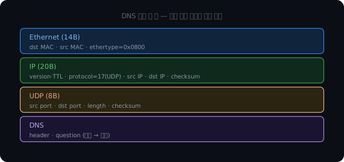
DNS 질의 한 장의 계층 레이아웃: 바깥부터 Ethernet 헤더(14B), IP 헤더(20B), UDP 헤더(8B), DNS 순으로 포개진다

결국 네트워크 스택도 메모리 위에 바이트를 차곡차곡 쌓는 과정입니다. 각 계층은 바로 아래 계층을 믿고 자기 헤더만 더할 뿐이고, 그렇게 완성된 패킷 한 장이 NIC를 통해 세상으로 나갑니다.

[ok] virtio-net ready, mac 52:54:00:12:34:56
[net] ARP who-has 10.0.2.2 (gateway) ... is-at 52:55:0a:00:02:02
[net] ping 10.0.2.2 ... reply
[net] DNS A example.com ... timeout (no outbound DNS?)
[ok] networking up: virtio-net + ARP + ICMP + IP/UDP

순서가 핵심입니다. 아래 계층이 동작해야 위 계층을 검증할 수 있고, 그래서 ARP→ICMP→UDP→DNS 순으로 쌓으면 검증도 그 순서로 누적됩니다.
신뢰성과 연결이 필요한 TCP는 10편 에서, 이 글에서 만든 IP·체크섬·드라이버를 그대로 딛고 이어갑니다.

코드: github.com/dj258255/kernel-hobby
다음 글: TCP: 연결 상태머신과 신뢰성 (10편)

참고 (1차 자료 우선)

0. Introduction

So far the kernel reached all the way to disk — boot, paging, processes, a filesystem, and multicore in Part 6.
Now the last piece: networking.

Networking has the widest code surface of all the xv6 labs.
From the hardware (the NIC — Network Interface Card) up through Ethernet, ARP, IP, and UDP, you have to stack the layers yourself before a single packet goes out and comes back.
The goal of this post fits in one line — feel, end to end, “how a packet is assembled from a byte array, goes out through the NIC, and returns.”

So this post builds the network stack in layer order, bottom up.
Lay the foundation with a NIC driver (virtio-net) that moves frames → resolve the gateway MAC with Ethernet/ARP → put IP on top → verify the IP layer with ICMP → add port multiplexing with UDP → finally resolve a domain with DNS.
We stack from the bottom layer up, because you can only verify an upper layer once the layer beneath it works — you can’t ARP without sending frames, can’t put IP on the wire without a MAC, and UDP is meaningless if IP is broken.

The test environment is QEMU’s user networking (SLIRP).
SLIRP is a virtual network that emulates a gateway (10.0.2.2), DNS (10.0.2.3), and DHCP, so it answers ARP, ICMP, and DNS without any host-side setup.
Our guest uses 10.0.2.15, the address SLIRP hands out by default.

This post’s stack goes up to UDP. TCP is deliberately deferred to Part 10. Doing the connection state machine, retransmission, and congestion control properly needs a whole post of its own. Why stopping here is reasonable is its own discussion in §6.

1. The real problem the virtio-net driver must solve

The CPU and memory only deal in digital signals. Yet physical work like “send this clump of bytes out over the wire” and “take the bytes that just arrived on the wire” — how does code make the NIC do that?

A NIC (Network Interface Card) is an external device.
Our kernel can’t wiggle the wires itself, so we need an agreed-upon way to give the NIC work.
On QEMU virt that agreement is virtio — a standard where the guest and a virtual device exchange work through ring data structures in shared memory.

One piece of good news — we already built a virtio-blk disk driver in Part 3.
The transport layer we built then (virtio-mmio: descriptor chains + available/used rings + feature negotiation) carries over to virtio-net almost verbatim.
Disk or network, the flow is the same: the guest builds buffers in memory, puts them on the available ring, rings QUEUE_NOTIFY, and polls until the used ring advances.

virtio-blk vs virtio-net — what’s different

They ride the same transport, but disk and network diverge in a few places.

Aspectvirtio-blk (disk, Part 3)virtio-net (network, this post)
device-id21
number of queues12 — queue 0 = RX, queue 1 = TX
header before each buffervirtio_blk_req (request header)12B virtio_net_hdr (checksum-offload / GSO info)
data directionread or write per requestRX is fixed device→guest, TX is guest→device
flowone request → one responseRX pre-stages buffers and polls; TX builds per send

net_init first scans QEMU virt’s 8 virtio-mmio slots (0x10001000, stride 0x1000) for the slot with device-id 1.
Then it raises the status bits step by step (ACKNOWLEDGEDRIVERFEATURES_OKDRIVER_OK) to wake the device — and that handshake is identical to the disk’s.

Feature negotiation — turn almost everything off on purpose

The device offers a pile of fancy features — checksum offload, GSO, merged buffers, a control queue. Which should we accept?

For a learning stack the right answer is “turn off as much as possible.”
Each feature you accept is code you then have to implement, so the more you enable, the more complex and bug-prone the driver gets.
So net_init keeps only VIRTIO_NET_F_MAC (read the MAC from config) in the low 32 bits, and accepts only VERSION_1 in the high 32 bits.

// low 32 bits: keep only MAC; turn off checksum / merged buffers / control queue
NR32(MMIO_DEVICE_FEAT_SEL) = 0;
uint32 lo = NR32(MMIO_DEVICE_FEAT);
lo &= (1u << VIRTIO_NET_F_MAC); // keep only MAC
NR32(MMIO_DRIVER_FEAT_SEL) = 0;
NR32(MMIO_DRIVER_FEAT) = lo;
// high 32 bits: accept only VERSION_1 (fixes the header at 12 bytes)
NR32(MMIO_DEVICE_FEAT_SEL) = 1;
uint32 hi = NR32(MMIO_DEVICE_FEAT) & 0x1; // bit 0 = VERSION_1
NR32(MMIO_DRIVER_FEAT_SEL) = 1;
NR32(MMIO_DRIVER_FEAT) = hi;

Turning off checksum offload means we compute the checksums ourselves (covered in §3).
Turning off merged buffers means one frame always lands in a single buffer, simplifying RX; accepting only VERSION_1 means the virtio_net_hdr is always a fixed 12 bytes, keeping parsing clean.
Code gets simpler at the cost of fancy features — a classic learning trade-off.

RX — hand buffers to the device in advance

Receiving has one asymmetry.
For TX you can build a buffer when you’re ready to send, but for RX you don’t know when a packet will arrive.
So RX pre-registers empty buffers with the device.
Stage 8 empty buffers in the RX queue, and when a packet arrives the device writes into one and bumps the used ring.
In other words the RX queue must always keep “available” empty buffers so the device can deposit a frame at any moment — so we refill a buffer right after handling it.

// register 8 RX buffers as device-writable
for (int i = 0; i < NUM; i++) {
rxbuf[i] = (uint8 *)kalloc();
rxq.desc[i].addr = (uint64)rxbuf[i];
rxq.desc[i].len = BUFSZ;
rxq.desc[i].flags = VRING_DESC_F_WRITE; // the device writes here
rxq.avail->ring[i] = i;
}
rxq.avail->idx = NUM;

The VRING_DESC_F_WRITE flag is the key here — it marks “this buffer is the side the device writes” (TX buffers lack this flag and are the side the device reads).
After that, eth_rx polls the used ring, and when used->idx advances it pulls the frame from the buffer, skips the leading 12 bytes (virtio_net_hdr), and returns that buffer to the queue (you must hand it back to receive the next packet).

// eth_rx — skip the 12-byte header on an arrived frame, return the buffer to the queue
uint32 len = e->len; // hdr + frame bytes
if (len > NETHDR) { // NETHDR = 12
flen = len - NETHDR;
copy(out, rxbuf[id] + NETHDR, flen); // skip virtio_net_hdr and copy
}
rxq.avail->ring[rxq.avail->idx % NUM] = id; // re-offer the buffer to the device

The MAC address is read as 6 bytes from the device config space (MMIO offset 0x100).
When init finishes, this line appears.

[ok] virtio-net ready, mac 52:54:00:12:34:56

Answer to the key question: the way code gives the NIC work is “put buffers on a shared-memory ring, ring the bell with QUEUE_NOTIFY, and poll the used ring” — exactly as with the disk. What’s new for networking is just two things: two queues (RX/TX) and a 12-byte header before every frame.

2. Ethernet and ARP — finding the first peer

Now that we can move frames, it’s time to actually talk to someone.
The first peer is the gateway (10.0.2.2).

The real problem ARP must solve

We know the gateway’s IP (10.0.2.2). But the recipient field of an Ethernet frame wants a MAC address, not an IP. How do we send the first frame to a peer whose IP we know but whose MAC we don’t?

Here’s the essence of layering.
Ethernet routes by MAC; IP routes by IP address.
These are different addressing schemes, so we need a translation step that answers “what is the MAC of the device with IP X?”
That translator is ARP (Address Resolution Protocol).

But there’s a chicken-and-egg problem — how do you ask when you don’t know the MAC? (The key to ARP is that you don’t ask one specific peer — you broadcast the question to the whole LAN.)
ARP’s answer is broadcast.
Shout “anyone on this LAN with 10.0.2.2? tell me your MAC” to everyone (ff:ff:ff:ff:ff:ff), and only the owner of that IP replies by unicast.

// "who-has 10.0.2.2" broadcast (28-byte ARP packet)
put16(a + 0, 1); // htype = Ethernet
put16(a + 2, 0x0800); // ptype = IPv4
a[4] = 6; a[5] = 4; // hlen=6 (MAC), plen=4 (IPv4)
put16(a + 6, 1); // oper = request
copy(a + 8, my_mac, 6); copy(a + 14, MY_IP, 4); // me, the sender
zero(a + 18, 6); copy(a + 24, target_ip, 4); // the target (MAC left blank)

arp_resolve sends this request, then polls the used ring waiting for a frame with oper=2 (reply) whose sender IP is the IP we asked about.
When it arrives, it pulls out the sender MAC (a + 8) and stores it.

We need the reverse direction too.
When someone asks for our IP (10.0.2.15), we have to reply (arp_maybe_reply).
Without it, a peer that wants to send to us can’t, because it doesn’t know our MAC.
So every receive loop that waits on ARP also services inbound ARP requests in the meantime.

// if an inbound frame is an ARP request for "our IP", send a reply
if (get16(a + 6) != 1) return; // requests only
if (!eq4(a + 24, MY_IP)) return; // not asking for our IP
put16(r + 6, 2); // oper = reply
copy(r + 8, my_mac, 6); copy(r + 14, MY_IP, 4); // "here's my MAC"
copy(r + 18, a + 8, 6); copy(r + 24, a + 14, 4); // send back to the requester

The boot log shows this conversation directly.

[net] ARP who-has 10.0.2.2 (gateway) ... is-at 52:55:0a:00:02:02

That one line appearing is a bigger event than it looks.
It proves, all at once, that a frame went out (driver TX + Ethernet encoding), a reply came back (driver RX + polling), and the ARP request/reply format was correct. In other words, both the broadcast request and the unicast reply succeeded.
It’s the moment §1’s driver and §2’s Ethernet/ARP interlock on a single line.

Common misconception fix: it’s easy to assume “ARP resolves the MAC of a far-off IP through routers.” It doesn’t. ARP only works within the same LAN (the reach of broadcast). Even when sending to a server across the internet, what we resolve via ARP isn’t that server’s MAC but the gateway’s MAC — hand the packet to the gateway and it routes from there. That’s why our stack can send every outbound packet knowing just the one gateway MAC.

3. IP, ICMP, UDP — stacking the layers

With the gateway MAC known, we layer protocols on top of the Ethernet frame, one at a time.

The real problem IP must solve

Ethernet only delivers between MACs on the same LAN. But how do you reach anywhere in the world, across LANs? And how do you know the clump of bytes that arrived isn’t corrupted?

IP defines a “globally valid address” (the IP address) that makes cross-LAN routing possible.
The IP header we build is 20 bytes — version/header-length (0x45), total length, TTL (64), the upper protocol number (ICMP=1, UDP=17, TCP=6), source/destination IP, and the header checksum.

A shared checksum — IP, ICMP, and UDP share one function

Corruption detection is the checksum’s job.
The internet protocols all agreed to use the same 16-bit one’s-complement checksum, so one function covers them all.

static uint16 cksum(const uint8 *data, int len) {
uint32 sum = 0;
for (int i = 0; i + 1 < len; i += 2) sum += get16(data + i); // sum 16-bit words
if (len & 1) sum += (uint16)data[len - 1] << 8; // odd-byte fix-up
while (sum >> 16) sum = (sum & 0xffff) + (sum >> 16); // fold carries
return ~sum & 0xffff; // one's complement
}

The receiver folds the whole header (including the checksum field) the same way; a valid header sums — with carries folded — to 0xFFFF (all ones), whose one’s complement is 0. So re-running checksum() and getting 0 means “uncorrupted.”
This one bit of arithmetic handles integrity for IP, ICMP, UDP, and TCP alike.

ICMP ping — the cleanest way to verify the IP layer

How do you confirm in one shot that the IP header is built right and the checksum math is correct?

It’s ping (ICMP echo).
Send an “echo request” (type=8) to the gateway and an “echo reply” (type=0) comes back.

// ICMP echo request — type=8, 32-byte payload, its own checksum
icmp[0] = 8; icmp[1] = 0; // type=echo request, code=0
put16(icmp + 4, 0xabcd); // id
put16(icmp + 6, 1); // seq
for (int i = 0; i < 32; i++) icmp[8 + i] = (uint8)('a' + i % 26);
put16(icmp + 2, cksum(icmp, 8 + 32)); // ICMP checksum
// → wrap in a 20-byte IP header (proto=1) and eth_tx to the gateway MAC

Here is one upside of the learning environment — SLIRP answers a gateway ping from inside itself.
So even without a single byte of outside internet, a ping round-trip alone proves our IP-header build + checksum + driver TX/RX are all correct.
You can verify the IP layer fully offline. (So the packet doesn’t actually reach the real internet — SLIRP answers in the gateway’s stead.)

[net] ping 10.0.2.2 ... reply

UDP and the pseudo-header — to whom, inside the same host?

IP is only responsible for “to which host.” But within one host, many applications — DNS, time sync, games — communicate at once. To whom inside should an arrived packet go?

That “whom” is the port number, and the simplest protocol that adds ports to distinguish applications (multiplexing) is UDP.
UDP puts just an 8-byte header (source port, destination port, length, checksum) on top of IP.

The UDP checksum has one quirk — the pseudo-header.
UDP sums not only its own header+data but also an imaginary header in front (source IP + destination IP + protocol number + UDP length) that it conjures up for the calculation.

// UDP checksum: pseudo-header (src IP + dst IP + proto + udplen) + the UDP segment
uint32 sum = 0;
sum += get16(MY_IP) + get16(MY_IP + 2); // source IP
sum += get16(dst_ip) + get16(dst_ip + 2); // destination IP
sum += 17 + udplen; // proto=UDP(17) + length
for (int i = 0; i + 1 < udplen; i += 2) sum += get16(pkt + 20 + i);

Why mix in the IP addresses?
It’s a design that double-checks “is this UDP segment really going for this source→destination pair.”
A safeguard to catch a packet whose header got mangled mid-flight and would be misdelivered to the wrong destination.
(For the record, Part 10’s TCP uses the same pseudo-header scheme — so learning it once in UDP, the TCP checksum follows for free.)

The layers on one screen

Here are the layers we’ve stacked so far. A single packet is the result of these headers nested like an onion.

LayerOur codeAddress / identifierHow it’s verified
Etherneteth_tx/eth_rxMAC (6B) + ethertype
ARParp_resolveIP↔MAC translationwho-has/is-at log
IPthe header in udp_tx/icmp_pingIP (4B) + protoheader checksum
ICMPicmp_pingtype (8/0)echo round-trip (ping)
UDPudp_tx/udp_rxport (2B)pseudo-header checksum

Key takeaway: every layer above leans on one and the same 16-bit checksum function. “Build a common mechanism well once and have several layers share it” is the very design philosophy of a real TCP/IP stack — small as our mini stack is, its structure resembles the real thing.

4. DNS — name to address

Finally, on top of UDP we layer DNS to turn a human-readable domain name into an IP.

The real problem DNS must solve

We want to reach example.com, but the IP layer only knows numbers like 93.184.x.x. Who bridges the gap between the names people remember and the addresses machines use?

That translator is DNS (Domain Name System).
The query goes to UDP port 53, structured as a header (marked as one question) + QNAME (repeated length-prefixed labels) + QTYPE (A=1) + QCLASS (IN=1).

// QNAME encoding: "example.com" → 7"example"3"com"0
while (name[i]) {
int start = i;
while (name[i] && name[i] != '.') i++;
q[p++] = (uint8)(i - start); // label length
for (int k = start; k < i; k++) q[p++] = name[k]; // label chars
if (name[i] == '.') i++;
}
q[p++] = 0; // terminate with the root label
put16(q + p, 1); p += 2; // QTYPE = A
put16(q + p, 1); p += 2; // QCLASS = IN

The trap in parsing the reply — name compression

Reading the reply has one trap — name compression (compression pointer).
Instead of repeating the domain name from the question, the reply points to it with a 2-byte pointer (0xC0..) meaning “that name already appears 12 bytes into the message, look there.” 0xC0 is binary 11000000when the top two bits are 11 it marks a compression pointer, and the remaining bits give the byte offset from the start of the message.
The same name shows up several times in a DNS reply, so it’s a bandwidth saver.
But the parser, every time it meets a NAME field, must distinguish: if the top 2 bits of the first byte are 11 it’s a compression pointer (2 bytes), otherwise a normal label sequence.

// answer NAME: a compression pointer (0xC0..) is 2 bytes; otherwise follow the labels
if ((r[off] & 0xc0) == 0xc0) off += 2;
else { while (r[off] != 0) off += r[off] + 1; off += 1; }
int type = get16(r + off); // A record if type == 1
int rdlen = get16(r + off + 8); // rdlen == 4 for A (4 bytes of IPv4)
off += 10;
if (type == 1 && rdlen == 4) { copy(out_ip, r + off, 4); return 0; } // found it

An asymmetry in verification — why only DNS times out

DNS has one decisive difference, though — it needs a real external network.
ICMP ping was answered by SLIRP internally, but SLIRP’s DNS (10.0.2.3) forwards the query to the host’s actual resolver.
So in an environment where outbound is blocked (a sandbox, say), the query goes out fine but no reply returns and it times out.

[net] DNS A example.com ... timeout (no outbound DNS?)

Here’s what must not confuse you — this timeout is not a bug in our stack.
Just before it, the successful ICMP round-trip already proved the IP header, UDP encoding, checksum, and driver TX/RX path are all correct.
The DNS query packet is built and sent down the same correct path — it’s only that the internet beyond SLIRP is blocked, so no reply can return.
In an environment with open internet, this very code prints example.com’s A record.

Common misconception fix: it’s easy to conclude “timeout = code bug,” but on a network you must read failures separated by layer. ARP succeeding means driver+Ethernet are fine; ping succeeding means IP+checksum are fine — once each lower layer is proven one by one, if only DNS fails, the suspect is not our code but what’s above it (the external network).

5. The boot demo — threading it into one flow

At boot, net_demo() runs the layers above bottom to top, once each in order.
That order is the order of verification.

void net_demo(void) {
// 1) ARP: resolve the gateway MAC (verifies driver TX/RX + Ethernet + ARP)
if (arp_resolve(GW_IP, gwmac) != 0) { ... return; }
// 2) ICMP: ping the gateway (verifies IP layer + checksum; SLIRP answers internally → OK offline)
if (icmp_ping(gwmac, GW_IP) == 0) uart_puts("reply\n");
// 3) DNS: resolve a domain (UDP TX/RX + DNS parsing; needs external network)
if (arp_resolve(DNS_IP, dnsmac) == 0) dns_query(dnsmac, "example.com", ip);
}

The key is that each step is a cumulative structure that verifies everything down to the layer just below it.
ARP working proves the driver and Ethernet; ping working proves the IP and checksum above them; the DNS query going out proves the UDP encoding above that.
The reward for stacking the layers in order is that verification, too, happens in order.

6. Why stop here — the up-to-UDP trade-off

This post’s stack goes up to UDP.
TCP is deliberately deferred to Part 10.
This isn’t laziness but an intended trade-off.

UDP vs TCP — what more is needed

AspectUDP (this post)TCP (Part 10)
connectionnone (fire and forget)3-way handshake (SYN/SYN-ACK/ACK)
reliabilitynone (loss ignored)ACK + retransmission timers
orderingnot guaranteedreassembled via seq/ack
flow / congestion controlnonewindow + congestion control
statestatelessa state machine per connection
header8 bytes20 bytes+

UDP is “attach a port and send” — done with an 8-byte header and a checksum.
TCP done properly, by contrast, needs a connection state machine, retransmission, reordering/reassembly, congestion control, and window management — a topic that eats a whole post on its own.

This series’ learning goal was “how a packet is assembled from bytes and travels.”
For that goal, ARP/IP/ICMP/UDP alone let you touch how the layers stack all the way from the NIC to the application, so stopping at UDP gave the best bang for the buck.
TCP’s state machine and reliability machinery are deep in their own right, covered separately in Part 10 — and happily, the IP header, pseudo-header checksum, and driver from this post carry over unchanged.

Key takeaway: in a learning system, “what you don’t build” matters as much as what you do. Foundations that lead straight into TCP — like the pseudo-header checksum — you lay early in UDP, but something independently heavy like a state machine you draw a boundary around and push to the next post.

Using polling instead of interrupts is the same flavor of choice.
A real NIC driver wakes on a receive interrupt, but for a single learning-oriented flow, polling the used ring is far simpler and easier to debug (the same policy as the disk driver).

Wrap-up

This post stacked the layers bottom to top, from the NIC driver up to an application protocol, and got to touch by hand the path of a single packet going out through the NIC and back.

  • virtio-net driver — on the same transport as virtio-blk, with device-id=1, two queues RX (queue 0) / TX (queue 1), and a 12-byte header before every frame. Turn off almost all features on purpose; RX pre-stages buffers and polls.
  • Ethernet + ARP — translate IP to MAC to find the gateway, and reply to requests for our IP. The single who-has ... is-at line proves driver+Ethernet+ARP at once.
  • IP, ICMP, UDP — a 20-byte IP header + a shared 16-bit checksum. A ping round-trip verifies the IP layer offline, and UDP adds port multiplexing + the pseudo-header checksum.
  • DNS — name→address translation over UDP. Parse the compression pointer, and read the timeout — separated by layer — as a blocked external network, not a code bug.

Folding the headers we explained separately into a single DNS query, it looks like this — the outer layers go out first:

Layered layout of one DNS query — from the outside in, Ethernet header (14B), IP header (20B), UDP header (8B), then DNS

In the end, a network stack is also just stacking bytes in memory, one on top of another. Each layer trusts the layer right below it and only adds its own header — and the one finished packet goes out through the NIC into the world.

[ok] virtio-net ready, mac 52:54:00:12:34:56
[net] ARP who-has 10.0.2.2 (gateway) ... is-at 52:55:0a:00:02:02
[net] ping 10.0.2.2 ... reply
[net] DNS A example.com ... timeout (no outbound DNS?)
[ok] networking up: virtio-net + ARP + ICMP + IP/UDP

The order is the point — you can only verify an upper layer once the one below works, so stacking ARP→ICMP→UDP→DNS makes verification accumulate in that same order.
TCP, which needs reliability and connections, continues in Part 10, standing directly on the IP, checksum, and driver built here.

Code: github.com/dj258255/kernel-hobby
Next post: TCP — the connection state machine and reliability (Part 10)

References (Primary Sources First)

Author
작성자 @범수

오늘의 노력이 내일의 전문성을 만든다고 믿습니다.

댓글

댓글 수정/삭제는 GitHub Discussions에서 가능합니다.